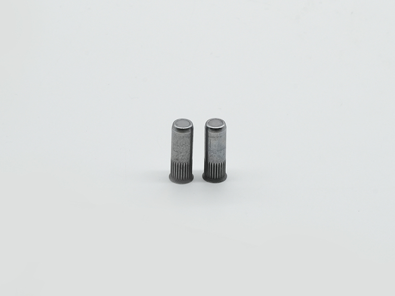
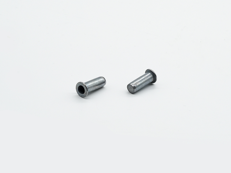
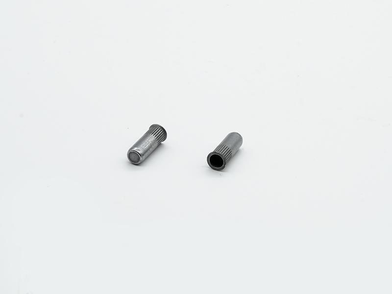
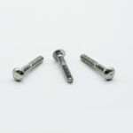
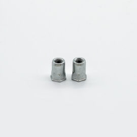
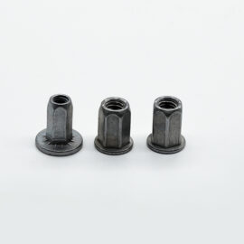
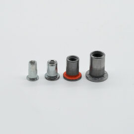
BSL® pull rivet nuts provide effective support for internal threads on automotive sheet metal.
BSL® pull rivet nuts provide an ideal solution for rapid riveting and internal thread support on prefabricated holes in automotive sheet metal. This series of fasteners includes a variety of structural types and different connection characteristics, and is widely used in various parts of automobiles with sheet metal as the substrate. Compared with welding methods, they can significantly reduce installation time and maintenance costs, are environmentally friendly and pollution-free, and do not cause overheating damage to the surrounding materials of the sheet metal substrate.
About pull rivet nuts
The structural design of BSL® pull rivet nuts includes anti-rotation structural design and sealing and waterproof structural design that adapt to different sheet metal hole types.
Usage scenarios
1) Flat head type, countersunk head type
The head shape is divided into two types: flat head and countersunk head. The flat head type is a general type, suitable for occasions where there is no requirement for the plane after installation; the countersunk head type is suitable for occasions where the plane after installation is required to be flat.
2) Through hole type, blind hole type (waterproof sealing)
The threaded hole design is divided into two types: through hole and blind hole. Among them, the blind hole nut can play a sealing and waterproof role in the threaded connection part, and is used in connection occasions that require sealing.
In order to further increase the waterproof performance around the connection hole after riveting, the root of the cap edge of the blind hole type product can be coated with glue to improve the overall waterproof performance of the connection.
size
| Product Code | D | L | d1 | dk | k | d | d0 | h1 | h |
| Blind Via | Blind Via | ||||||||
| Nominal | refer to | refer to | refer to | Max | Max | +0.1 | refer to | refer to | |
| B1022-YWM-050135 | M5 | 13.5 | 5.6 | 8 | 0.6 | 6.98 | 7 | 11.3 | 0.5~1.0 |
| B1022-YWM-050145 | 14.5 | 1.0~2.0 | |||||||
| B1022-YWM-050155 | 15.5 | 2.0~3.0 | |||||||
| B1022-YWM-050165 | 16.5 | 3.0~4.0 | |||||||
| B1022-YWM-060175 | M6 | 17.5 | 7.5 | 10 | 0.6 | 8.98 | 9 | 14.3 | 0.5~1.5 |
| B1022-YWM-060190 | 19 | 1.5~3.0 | |||||||
| B1022-YWM-060205 | 20.5 | 3.0~4.5 | |||||||
| B1022-YWM-060220 | 22 | 4.5~6.0 | |||||||
| B1022-YWM-080205 | M8 | 20.5 | 9.2 | 12 | 0.85 | 10.98 | 11 | 17 | 0.5~1.5 |
| B1022-YWM-080220 | 22 | 1.5~3.0 | |||||||
| B1022-YWM-080235 | 23.5 | 3.0~4.5 | |||||||
| B1022-YWM-080250 | 25 | 4.5~6.0 | |||||||
| B1022-YWM-100245 | M10 | 24.5 | 11 | 14.5 | 0.85 | 12.98 | 13 | 20.2 | 0.5~1.5 |
| B1022-YWM-100260 | 26 | 1.5~3.0 | |||||||
| B1022-YWM-100275 | 27.5 | 3.0~4.5 | |||||||
| B1022-YWM-100290 | 29 | 4.5~6.0 |
Performance Table
| Thread specification D | Thread load protection (N) |
Head binding force (N) |
Shear force (N) |
Breaking torque (N.M) |
Rotational torque (N.M) |
| Nominal | Min | Min | Min | Min | Min |
| M5 | 11500 | 4348 | 2600 | 8 | 1.5 |
| M6 | 16500 | 6149 | 3800 | 15 | 3.5 |
| M8 | 25000 | 9034 | 5400 | 26 | 4.5 |
| M10 | 32000 | 11926 | 6900 | 45 | 8.5 |
Surface treatment
Since the rivet nut achieves its connection function by clamping the plate through plastic deformation caused by local extrusion of the product, the processing method is usually cold extrusion molding, so the selected material must have good plasticity and meet certain connection strength requirements.
Installation Method
1.1 Product installation steps
1) Select a pneumatic rivet nut pulling riveter with matching pulling force, install a screw of matching specifications, and adjust the appropriate pulling stroke according to the installation thickness and tool manual;
2) Load the product, perform an empty pulling test, verify whether the stroke is appropriate, and reserve the stroke appropriately according to the sheet metal thickness;
3) Perform a real riveting test on the test sheet metal, as shown in step 1 below.
4) Observe whether the clamping state of the product after installation is normal.
5) (To determine whether the installation fails, please refer to the following article – Product installation failure mode pictures)
1.2 Operation steps
Hold the product and align the screw head of the tool from the flange end, apply initial pressure, and note that the product should be kept in a vertical direction. At this time, the tool screw automatically screws into the product nut. The flange surface of the product needs to be close to the tool plane, and then the tool is inserted into the mounting hole in a direction perpendicular to the sheet metal plane and close to the sheet metal surface. Then the trigger is pulled, and the screw rotates forward to start riveting. After the stroke reaches the end, the screw automatically rotates back in the opposite direction. At this time, one riveting action is completed, and then the next working cycle is carried out.


